XJ6R – Steering Rack

Steering rack

I decided to rebuild the steering rack whilst I had easy access to it with the engine out. The bushes were “cream crackered” as can be seen by the photos. I had some replacement Poly based bushes that came with a car I purchased years ago. The bushes are in fine condition so I used those. The old bushes were pushed out using a couple of sockets and a threaded bar to get it moving and eventually gently tapped out. The new ones were pushed back in and I am just awaiting delivery of the rack rebuild kit.
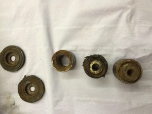
Knackered bushes
Knackered bushes

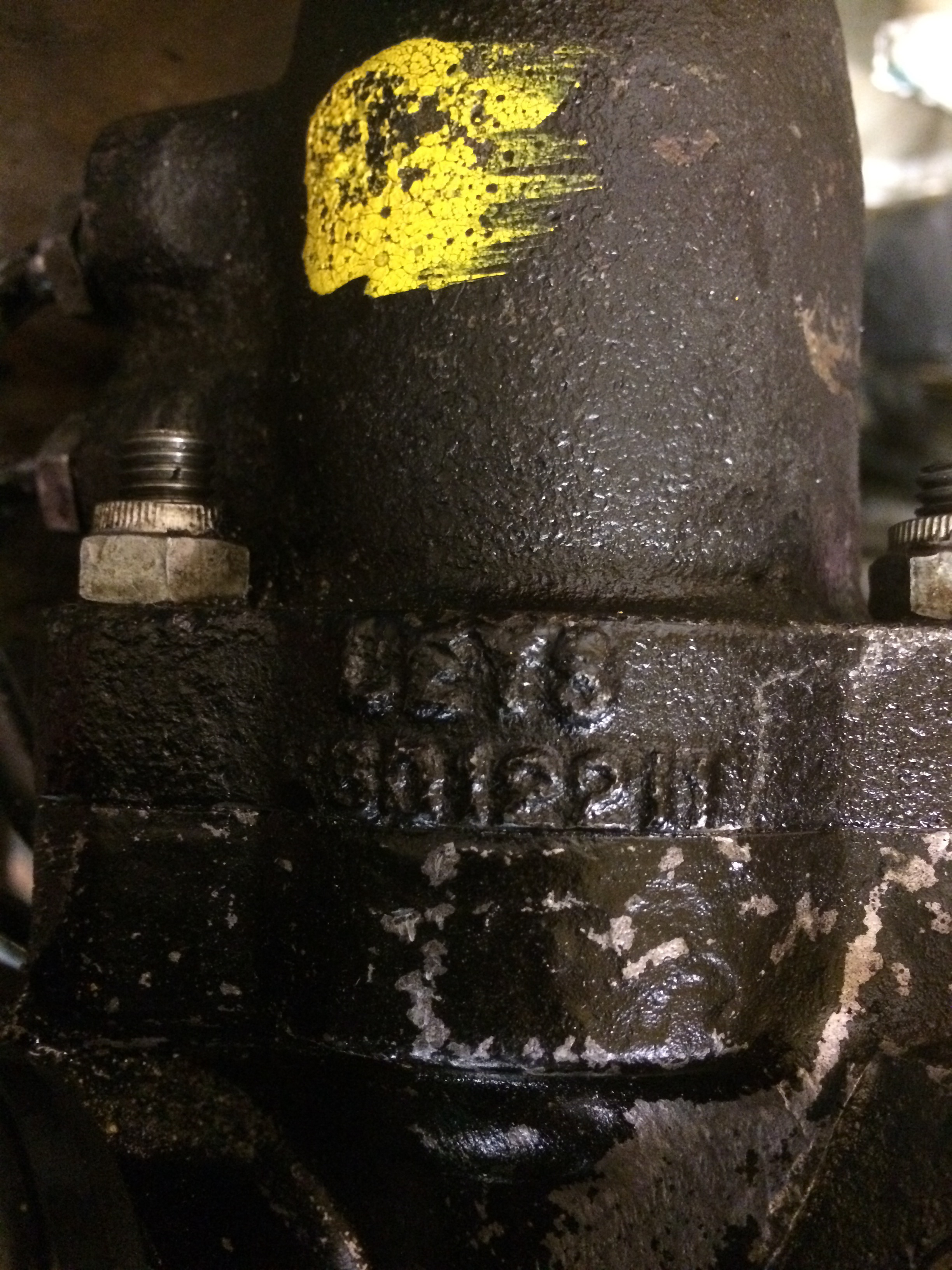
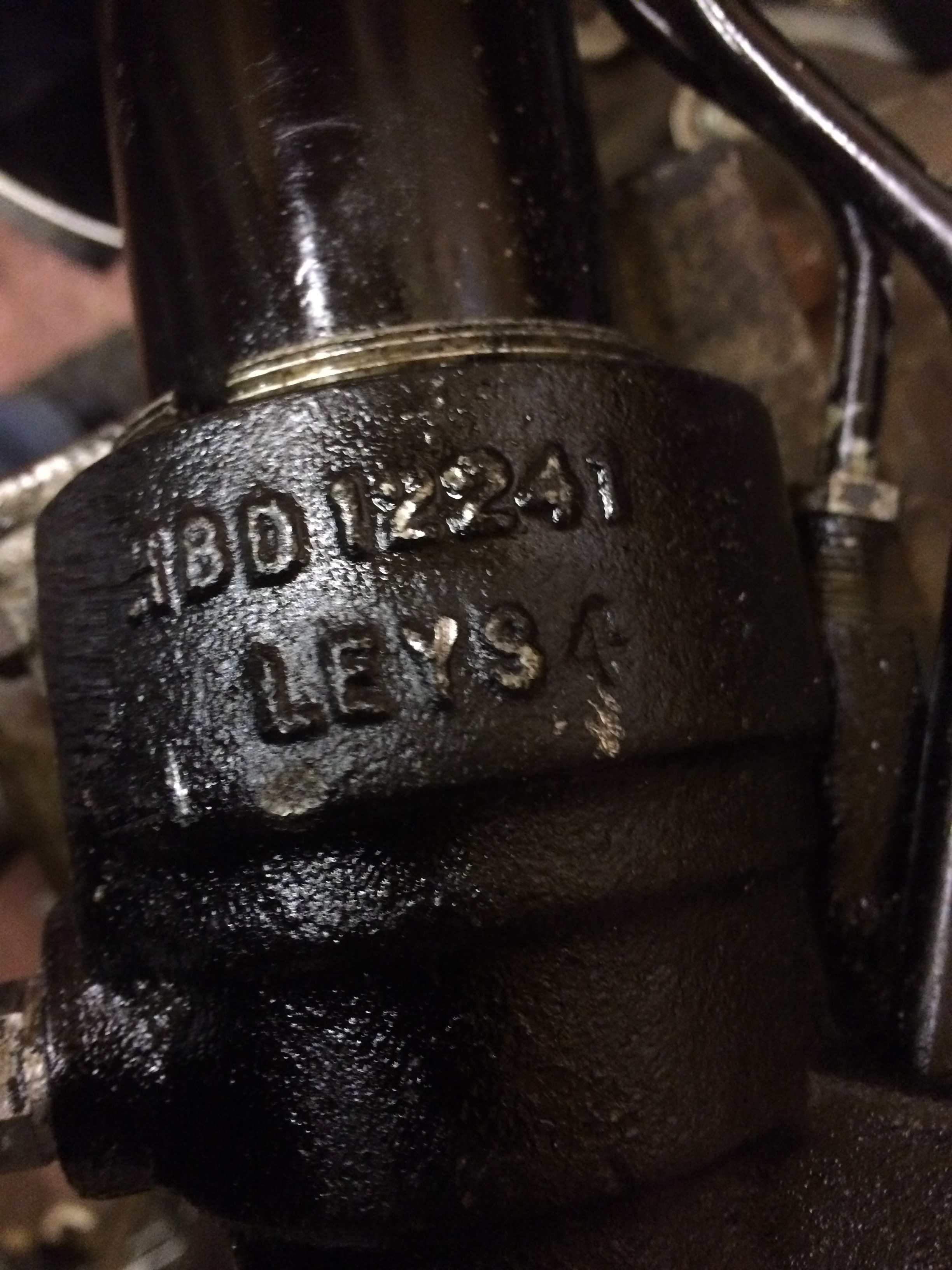
The first challenge was to identify the rack type. There are a few variations on steering racks over the years and it was not straight forward to identify the one straight away. I did a little searching on the internet and through the parts/service manuals and got the impression I had the Adwest manufactured part. A close look at the steering rack once it was cleaned up and on the bench revealed a few words and numbers cast into the rack. You can see these in the photos below:
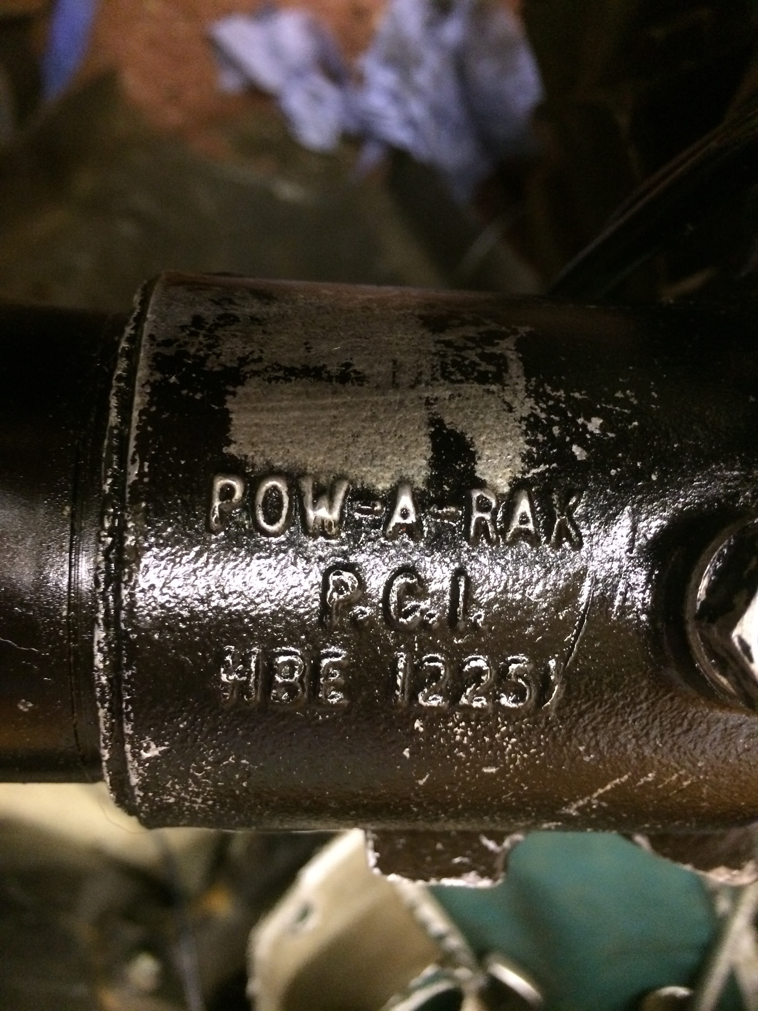
HBD 12251
HBE 12251
HBD 12241
HBD 12241
HBD 12211
HBD 12211

I found the following identifiable words/numbers POW-A-RAK and three numbers HBE12251, HBE 12241 and HBE 12211. A little more searching on these and I found this page which lists the casting numbers as ADWEST CAST NO HBD12241- HBE12251- HB12211.

Also this site listed the parts as Adwest too.

JAGUAR 1973-79 XJ6/12 80 cm Short Pinion Series 2 & 3 Adwest HBD 12211, 12241, HBE 12251 & HBE 16400 P2318 NAK8076

Compare the pictures with those in the parts manual and the repair kit part number is AAU1503. I have ordered a repair kit and new bellows to finish off the job. As it happens I also have a spare steering rack from an older S2 XJ6 which is the Alder type so I should be able to rebuilt at least one of then regardless 🙂
XJR6 – Fuel Pipe installation

Fuel Pipe installation

As previously mentioned, I planned to fit the fuel pipes today having finally decided how/what I was going to do!

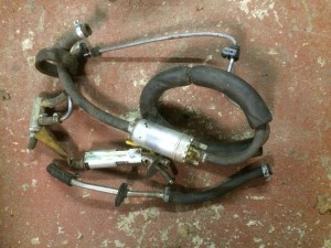
I did spend at least an hour or three looking through cupboards and boxes for the Series 3 valves. I gave up and started working on the pipes. I did find some of the S3 fuel system parts as per below, but not the valves. I know I have them somewhere as I can picture moving them a few times but they are hiding at the moment.

S3 Fuel pump and pipes
S3 Fuel pump and pipes. All the bits I dont need!

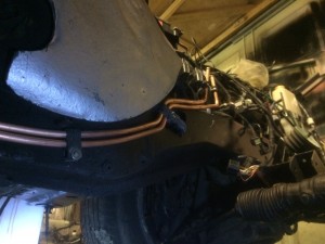
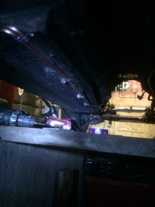
I did then work out a route with very little modification to the body save a few screw holes and a minor trim of a flange along the floor. The two pipes are fixed approximately every 12 inches using either modified (cut smaller) versions of the XJR pipe clips or new Stainless rubber covered P clips. There is still a little tidying up to do to make them look a little straighter but they are in place.

Piping - view from the rear
Piping – view from the rear
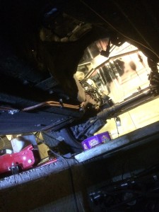
Pipes existing the tunnel
IMG_2535
Pipes where they cross over into the transmission tunnel (minor trim of the floor flange required)


I have made up a couple of pipes to go up and over the rear suspension cage and into the spare wheel space in the boot. I will have to drop the cage down a little to install them so I did not manage to get to that today. The pipes in the photos and the two going over the suspension cage will be joined using short rubber pipe sections. The copper ends of the pipes should exit into the boot area. There is quite a large round grommet already there which I will try to use but if unsuccessful there is a large rectangular removable panel that I could put the pipes through if needed. I think these panels are there to assist in changing the awful handbrake pads which are almost impossible to change without dropping the suspension cage.

XJ6R – Fuel System Finalised

Fuel System Finalised

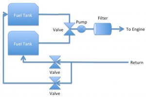
After some research, discussions, Email and yesterday over the phone with my Nephew who is a car mechanic and has done numerous engine swaps, I have come to the decision to Keep It Simple Stupid or KISS! In essence, I will replace the two internal pumps, one in each tank, with a pick up pipe and then feed the two outlets via a three way valve to a single, high performance pump. The tanks already have their own vents. This is pretty much how a Series 3 XJ6/12 fuel system is designed. I am sure I have the appropriate S2/S3 valves “somewhere” in the garage. It should end up looking something like below:

Fuel system - Anticipated end design
Fuel system – Anticipated end design

Todays tasks

  • Run two new fuel lines from the engine bay back into the boot area
    • The original fuel lines ran down the drivers side. The XJR lines ran down the passenger side. This means I have to find a new route that has some protection from the heat of the exhaust, the potential for damage from the drive line and and of course the ground such as speed bumps etc.
    • The biggest challenge will be getting the lines over the rear suspension cage and into the boot area
  • These two lines will be the fuel out and return lines and will use new copper fuel pipes plus the rubber end pieces from the original fuel lines so they connect into the engine fuel rail as per before.
  • Remove the two internal pumps from the two XJ6 tanks and make up a pick up pipe for each tank that will collect the fuel from the lowest area of each tank.
  • Each of those pipes will go via the original three way Switch Over Valve to a new high performance pump.
  • The outlet of the new pump will go to a filter
    • The fuel filter will be the the standard XJR filter (which I have a couple of new ones already)
  • Then the fuel out line will connect to the filter on onto the engine bay
  • The return lines will go back to the appropriate tank via the original Switch Over Valves.

“Simples” 🙂

Thanks to James G. and Richard B. for their knowledgable input.

I’ll post the progress as soon as it is done.

Pipe Installation