Brake Master Cylinders
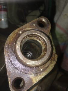
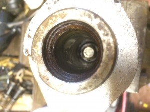
I spent some time in the garage over the weekend. Most of it was spent inspecting the Brake Master cylinder for the car. I had a pair of these for the XJ6. One I rebuilt, maybe 15 years ago and put in a drawer and the rusty looking one that was the original still in the car. The rebuilt one looked OK externally but had the wrong rubber fittings on the top where the reservoir should sit. It had the two identical rubber fittings that I believe go to the later versions of the car. These had a separate reservoir attached to the bulkhead via two pipes. My car has the reservoir fitted directly on top of the master cylinder. I had problems getting the pins out that hold the reservoir onto the master cylinder. I ended up cutting and eventually drilling out one of the pins. I then started to disassemble the cylinders themselves. The original master cylinder was very rusty and took a little persuasion to disassemble. Having removed the first of the two plungers, a quick look inside at the cylinder wall proved that it was beyond repair. I think you can see the rust damaged cylinder walls in the photos.


I then started on the one that had new rubbers fitted years ago to see if that was in a usable state. Unfortunately not! It looks like a new master cylinder is needed. They are no longer available from Jaguar Heritage. A quick look through the suppliers I often use reveals that there are superseded items available. Not a cheap item but better safe than sorry!
ODBII Socket
As I could do no more to the braking system, I spent a while reviewing some of the wiring and finally decided where I would place the ODBII connector. It is going to go inside the drawer in the central arm rest, between the driver and passenger seats. Not too difficult to wire up, deciding on where to put it took longer than wiring it 🙂 I was initially looking at somewhere under the dash but the centre console seems a better place. I will no doubt require access to it quite frequently, at least in the initial stages of installing and getting the engine running. I still need to check for clearance under the drawer as there are a couple of large pipes feeding the heating/AC flow to the rear of the car. I have left a fair amount of slack in the wiring to allow a lot of positioning options just in case.
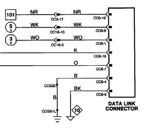
There are just a few connection needed.

Brown/Red – Box 101 is a fused but constant +12v supply
White/Pink – Circle 5 is a switched +12v when key is in position 2 which is normal running position
White/Orange – Hexagonal 3 is a switched ground signal also when the key is in position 2
Pink and Orange are CAN bus serial data lines
Black is chassis and Black/Pink is logic ground.
I had previously wired/reserved the constant +12v, and the switched +12v using the fuse box I installed into the passenger foot well by the door hinges. I had also implemented a relay to provide the switched ground connection elsewhere so I just tapped a wire off of that feed. The rest were either available to tap into around the J-Gate assembly or running across the area to get to the Instrument PCB. The Instrument PCB is going to be installed vertically on the drivers side of the centre console.
1 Response