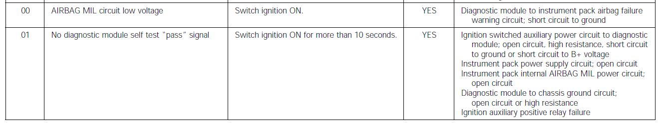
Airbag Module Output Signals Uncovered
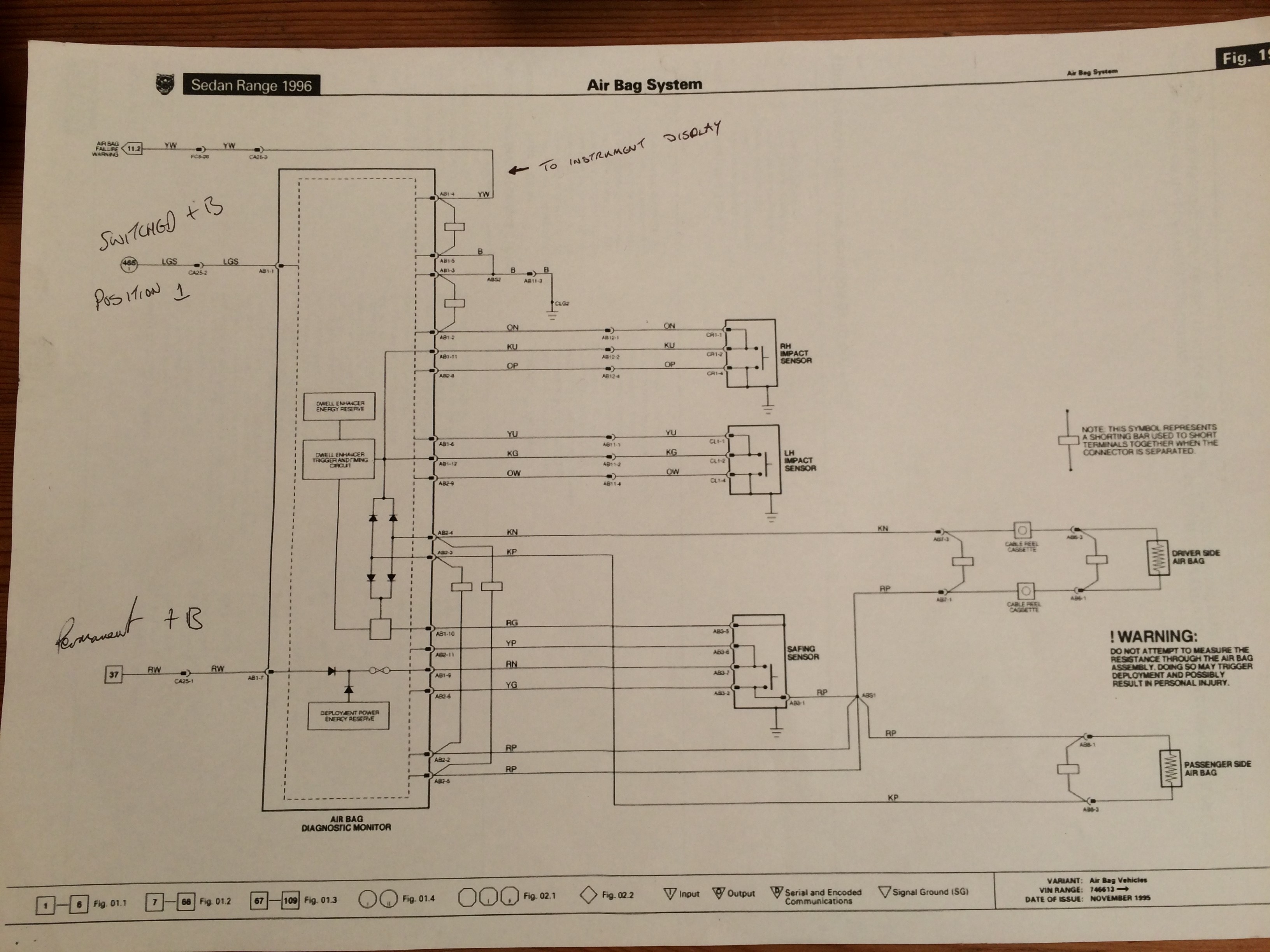
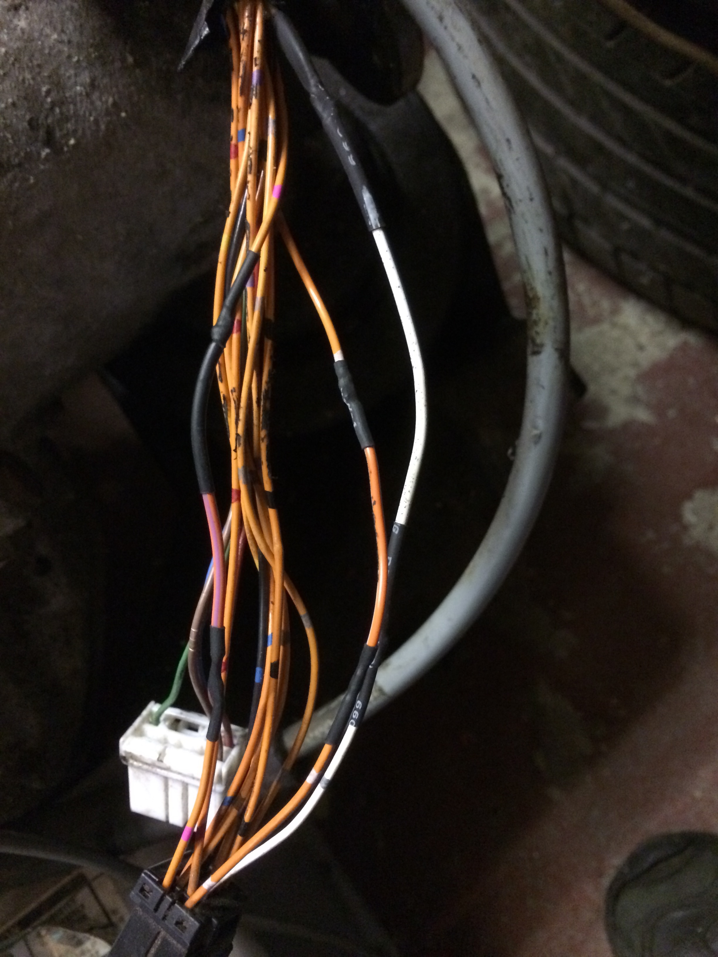
Following on from my previous post on the airbag warning message, I did some testing of the Air bag Module (ABM) today. I identified the correct output signal that the Instrument panel expects following a “power on” of the ignition system. First, I used the original, yellow sheathed Airbag wiring loom and some resistors to fake the existence of Airbags. It turns out that the steering wheel Airbag reads approximately 1.2 ohms when in good condition.
WARNING!
Please be very careful when doing anything with “live” Airbags, they are dangerous hence I used resistors instead. Please, Please view any one of a number of videos available on the subject at the well known online video site prior to connecting anything electrical to an Airbag. If you do not know what you are doing, get someone who does. I suggest you do not touch them at all. I have measured mine so you don’t have too. Just keep them locked away somewhere safe or dispose of them safely. Do not come back to me of one goes off accidentally, you have been warned!
I did not have any 1.2R resistors. I ended up using four 6R resistors in parallel and just pushed them into the appropriate plug in the loom. It took a little debugging to stop the Airbag module from buzzing an error code. Once I had the rig working, I could see what the output signal should be in normal operation. The issue I had was that the Safing module does not have a separate wire for its ground connection. It relies on the connection to the chassis via the mounting bolts. As I had the module sitting on a wooden panel, I needed to provide it with a separate ground to get it working.

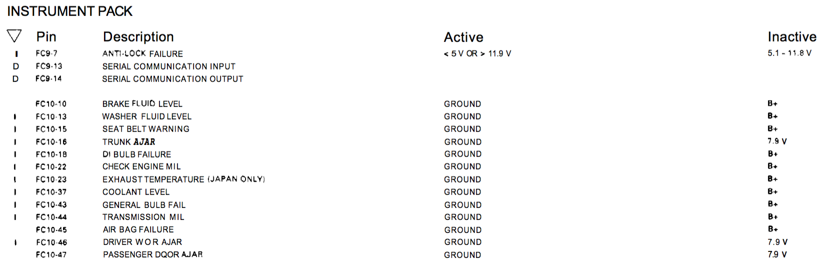
As expected, it turns out that although the circuit diagram says Ground and +B as the active/inactive conditions the reality is a little more complex than that.
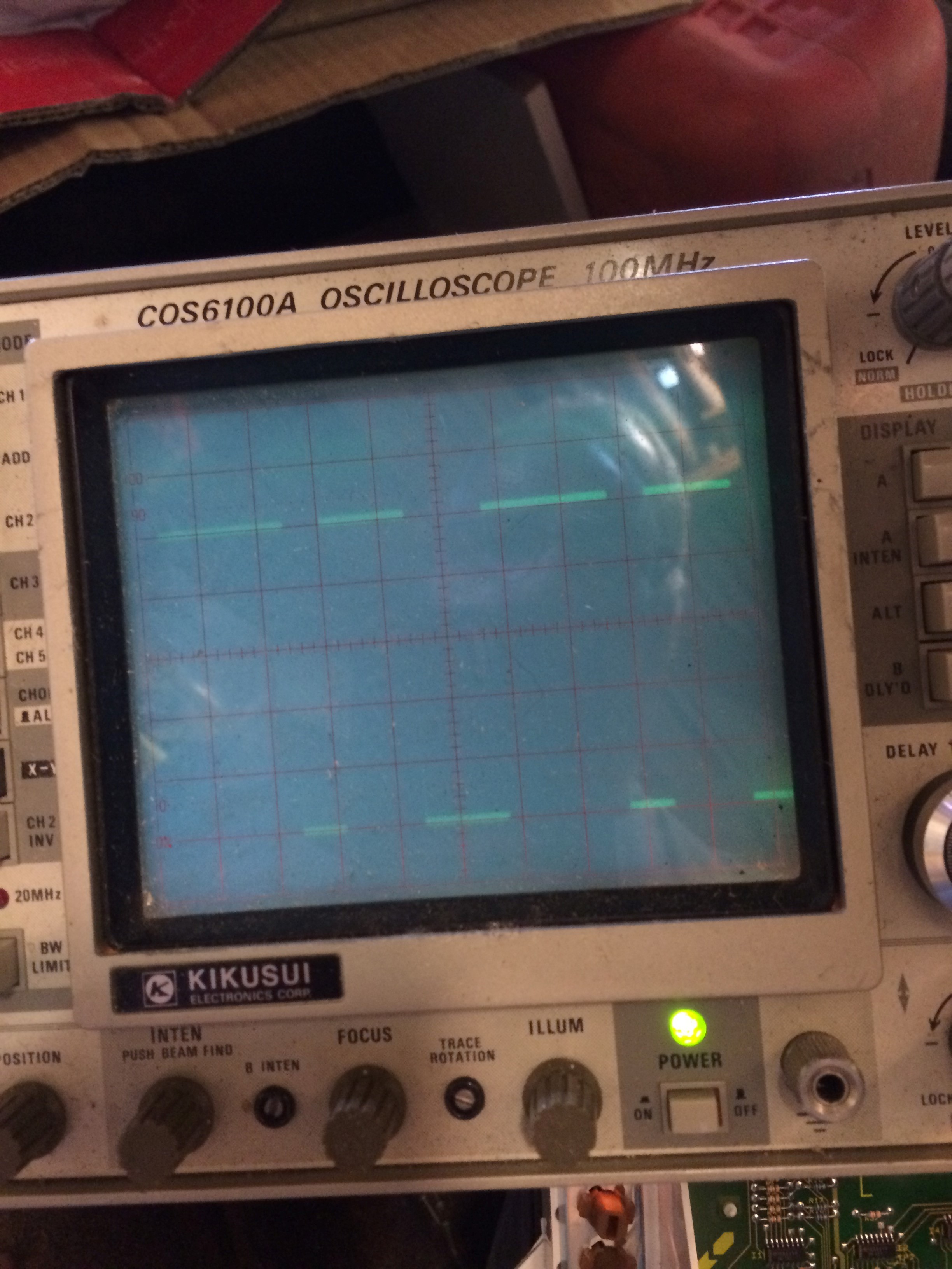
- With power permanently applied to the module the output signal is +B
- Turn on the ignition power and the signal drops to ground for approximately 10 seconds
- This is the Self test Pass signal “sequence” I was unaware of prior to this test
- After that, the signal returns to +B and remains there unless an error is identified
- I did try disconnecting the resistor packs (pretending to be the Airbags) one at a time and the signal goes from high to low as follows:
- 3 times high to low
- A short pause at high
- Followed by either two or three high to low again depending on which “airbag” (actually a resistor pack) was disconnected
- It then repeats the sequence again until the problem is resolved
- This, I presume, equates to error codes 32 or 33 which is similar to the way the error code was displayed by the ABS module on my old XJS. It flashed the ABS light on the dashboard after you shorted a couple of pins together on the ABS module
The question is now, do I generate the same signals using just a few components or do I hard wire the required signals and use the Airbag module?
Debugging the Transmission MIL light
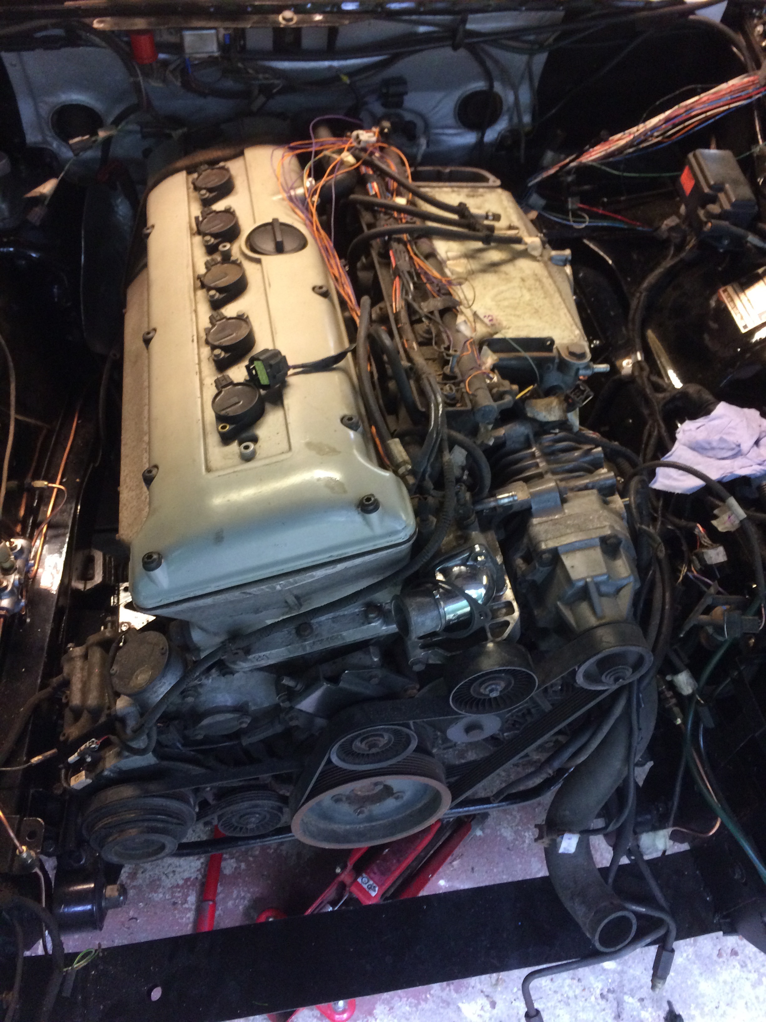
Having identified the requirements to resolve the AIRBAG warning on the digital display. It was time to look into the Transmission MIL light issue. First there was the connection of the transmission loom to the transmission control module. I removed the panel below the gear leaver assembly which enabled me to push the transmission wiring connectors through a hole in the tunnel and connect up to the transmission module. The transmission error light was still taunting me! I did a slight tidy up of the wiring and re-connection of the Transmission module ground but still had the error. A little more debugging and discovered that I had not connected the permanent power feed to the transmission control module. I connected this up to the appropriate permanent feed, the MIL light went away.
Another problem resolved 😉