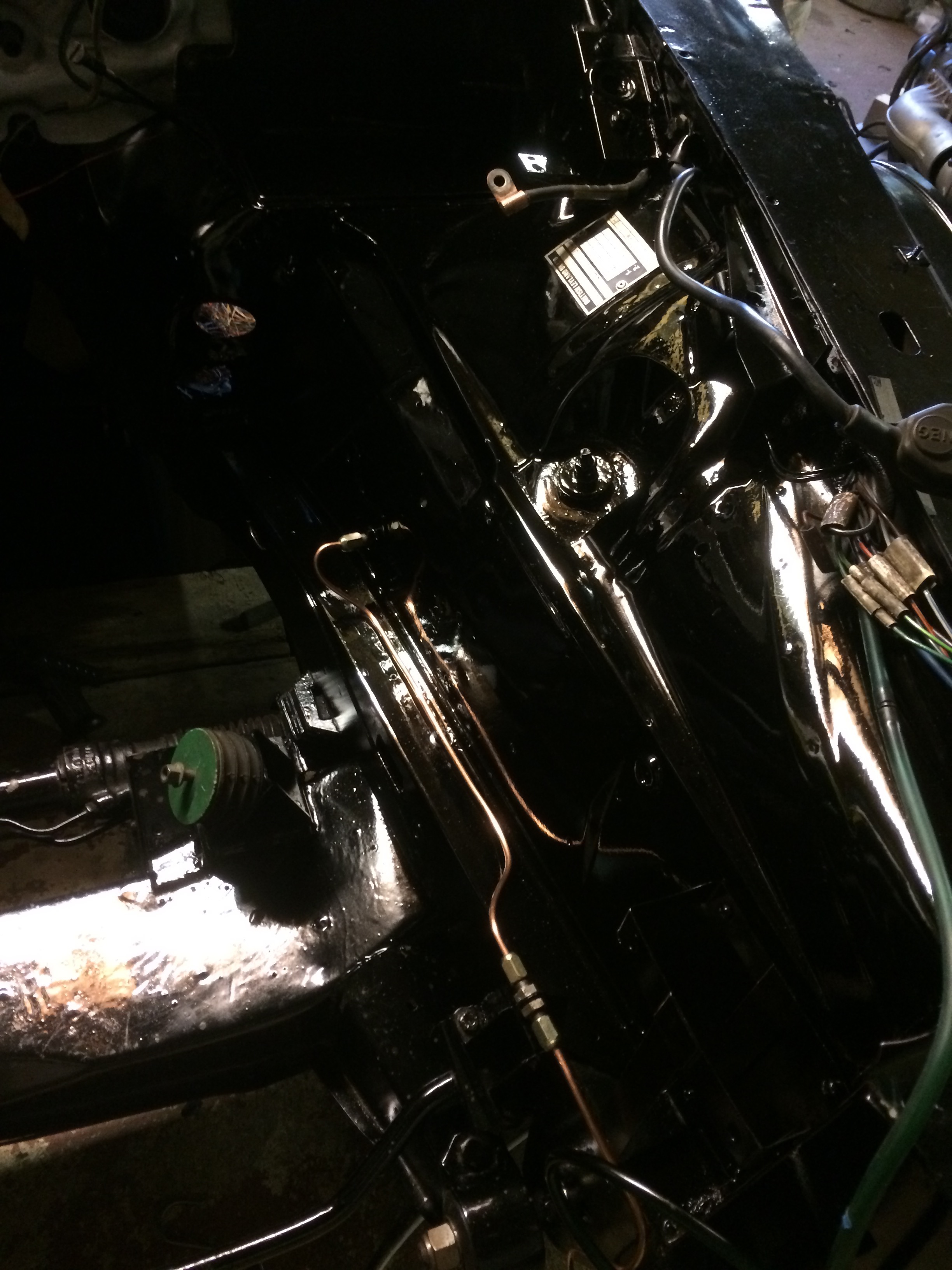
last weekend I started on the inner wing refit. I added a relay mounting plate for three relays (ECU power, Starter Motor and Ignition coils) I also refitted the Alternator “Suppressor” along with the components for the Evaporative system. The cabling was tidied up and clipped back to make it look more presentable. You can see the difference between the before and after photos below. Not long now before I can refit the Engine. Yipee!
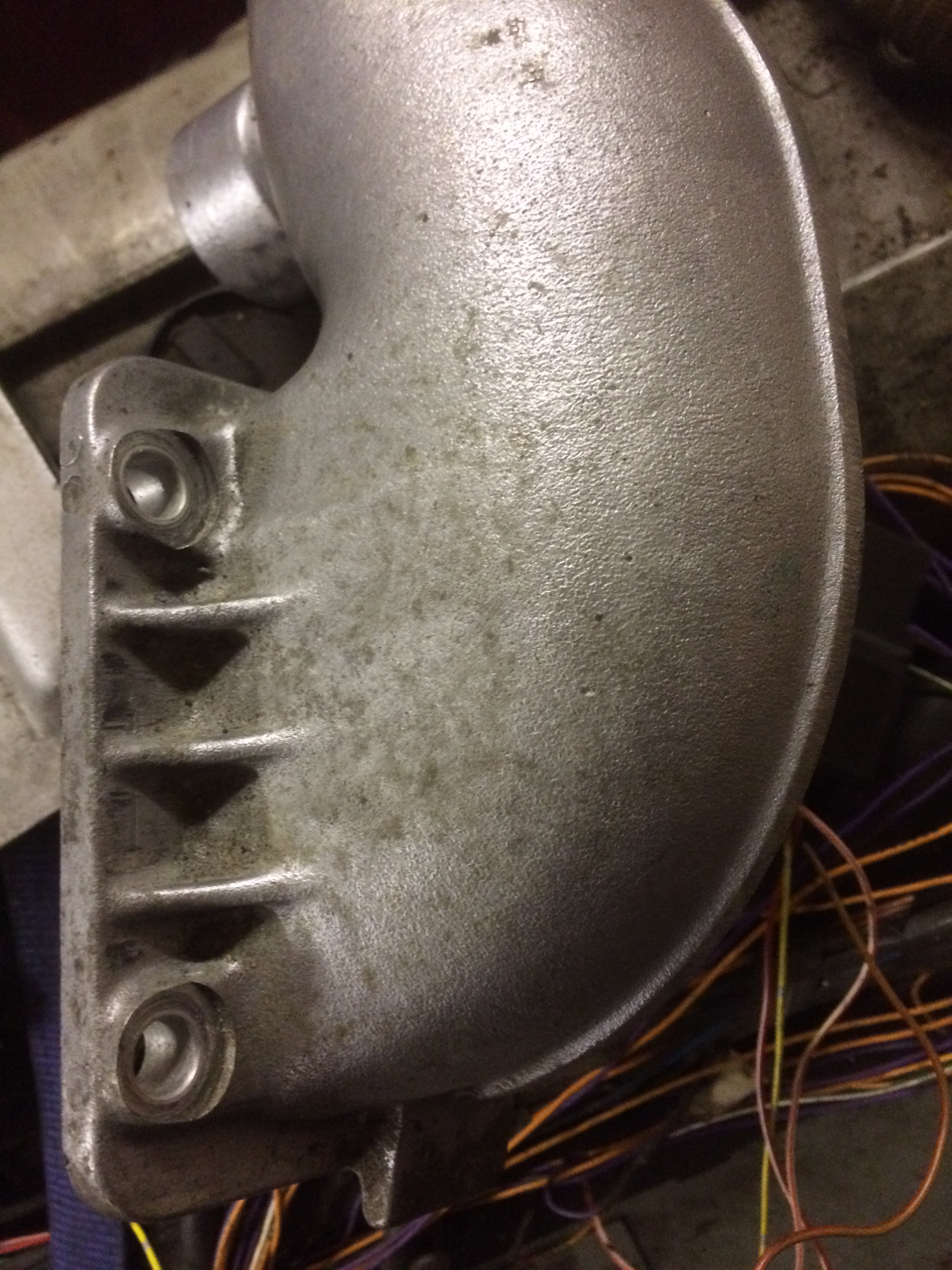
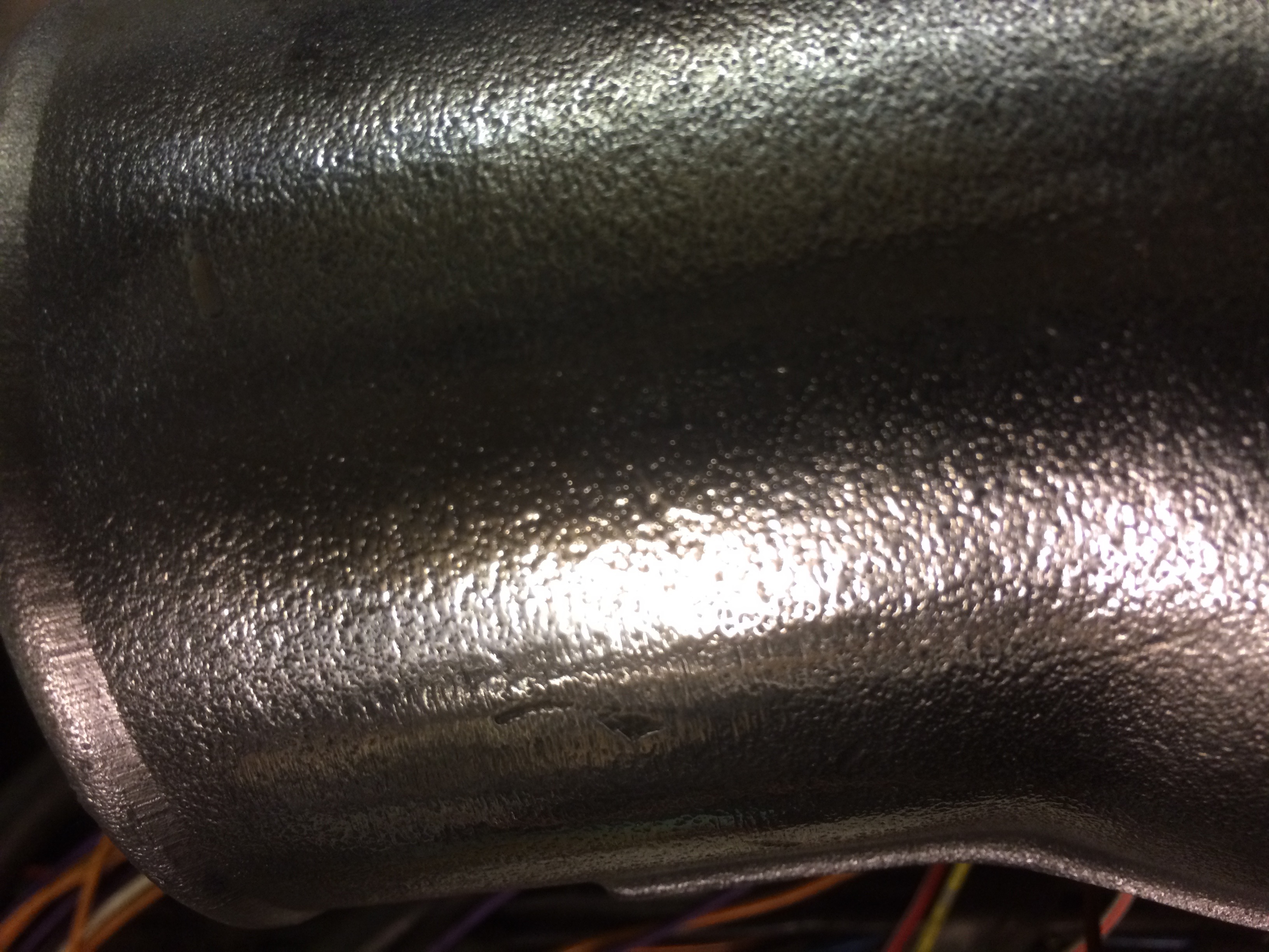
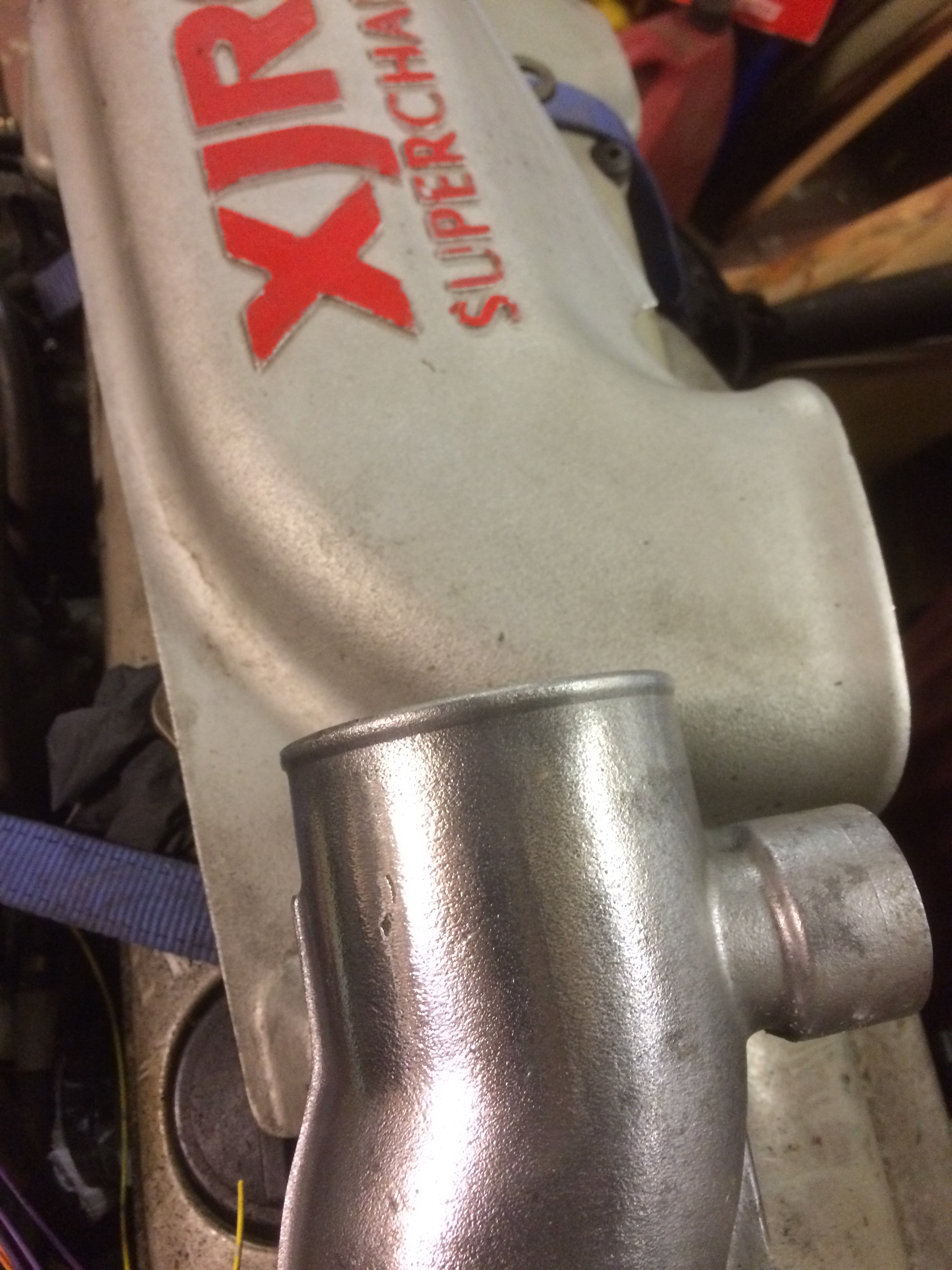
As mentioned previously (at the end of the post), I have seen an XJR6 engine in a polished state rather than the greyish silver that the engine originally came in. Having just purchased a bench polisher, I did a quick test of one of the air pipes (on the underside where you would not normally see), to get an idea of the possible outcome. Please view the images below and provide any feedback with your views. Any arguments over originality disappeared the moment I decided to do the engine swap. I think the only choice is to polish or try and find a spray paint that closely matches the original colour. Not an easy task. I cant clean up the original surface much more than the first photo without braking through the surface colouring. I think the “sand” finish provides extra surface area so it may improve cooling but at the end of the day I doubt if I could notice the tiny percentage in performance difference even it I sanded the surface flat and did a major polishing job. Does anyone have any idea of the paint colour code? I am going to have to decide very soon as this is stopping the installation back into the engine bay.
Pipe just degreasedPipe following a quick polishClose up detailtop cover and polished pipe
A fellow Jaguar enthusiast and I went to the London Classic car show at the Excel centre in London on Saturday. It was pretty busy for most of the day, so much so that during the parade sessions it was almost impossible to get a decent view. The very brief video at the end of the article shows that there were people three rows deep between the casual observer and those keen to ensure a good view by grabbing a front row view early. I did however like the idea of the “road” down the middle of the hall to allow for a bit of noise and excitement during the day.
E types definitely ruled the roost as there seemed to be at least one or more on every stand. Judging by the prices that some of those were listed for it is unlikely that I will ever be able to afford something like that. At the same time however, I don’t actually want a car that I can’t drive for fear of getting it dirty and loosing a massive amount of value. What’s the point of owning a £250,000 car if all you can do is keep it in a temperature controlled garage with the occasional visit to a show, taken by trailer of course. It takes all sorts of course and investing in a E Type has probably increased more in value compared to what you would receive leaving your money in the bank over the last few years.
I did expect to see more parts and component suppliers but I guess the costs for a stand these days is fairly high. One of my usual parts suppliers S N G Barratt were there and if I had got my act together I could have saved some postage on the parts I need. I would also have had to carry them around all day too.
There was another show going on in one of the adjacent halls which was similar to the Comicon type event. It was the London Super Comic Convention. Hundreds of colourfully dressed people wandering around certainly brightened up the day. I applaud those visitors who made the effort as I am well aware of the time needed to create the various outfits as my daughter attends these shows quite regularly.
It was certainly a different kind of car show to those I normally attend, if only for the sheer restoration quality of the cars on display. I doubt if I will go again as most of the cars were out of my reach financially and I was unable to to find any of those little bits and pieces I need as part of the ongoing Jaguar rebuild.
DIY was the order of the day for Sunday so no progress this weekend on the XJ6 either.
Here is a 10 second video of the noise reverberating in the hall from an Audi Quatro rally spec car. A bit of movement and noise makes a big change from the static displays. The Lotus F1 car and a Subaru WRX sounded great too but unfortunately I have no video.
I managed to get a few short hours in the garage over the weekend when it was not raining outside. I needed it to be dry so that I can put my small compressor outside to feed fresh air to the face mask. I had done some wet sanding to get rid of the worst of the paint runs (from part 1) and of course I had gone through the paint and back to the metal in a couple of places. I re-masked off the various parts and resprayed the inner wing again. Although not as good as I would like, it is passable. Especially as this is the side where the Supercharger goes, along with a few ancillaries so there is not a lot of room left for you to see any bad paint work! I will let it harden for a few more days and give it a light buff and polish. Apologies for the picture quality, trying to show a paint finish is very difficult at the best of times but this is black in a fairly dark part of the garage. Also the phone camera is not that good either.
Inner Wing
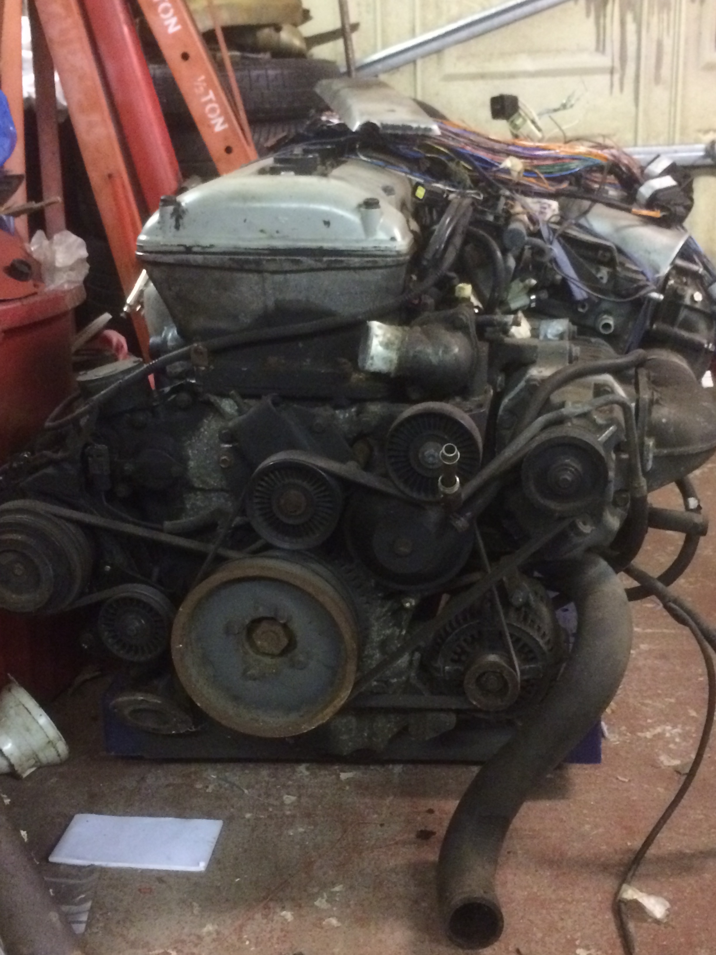
I also made a start at cleaning the engine up a little as it looks quite a mess. I removed some of the metal work that makes up the inter-cooler air feed pipes and washed them in solvent. They do look a lot better but I might have to resort to polishing them or even spraying them. They are aluminum but have a kind of textured finish to them. I guess that there is more exterior surface area meaning that it might allow more cooling from passing air? I was wondering what other people have done with these engines. I did see an E-Type with a fully polished (very shiny) XJR6 engine installed so maybe that’s the extreme.
Engine prior to cleaning
It is -2 outside so I will do some more research and planning!
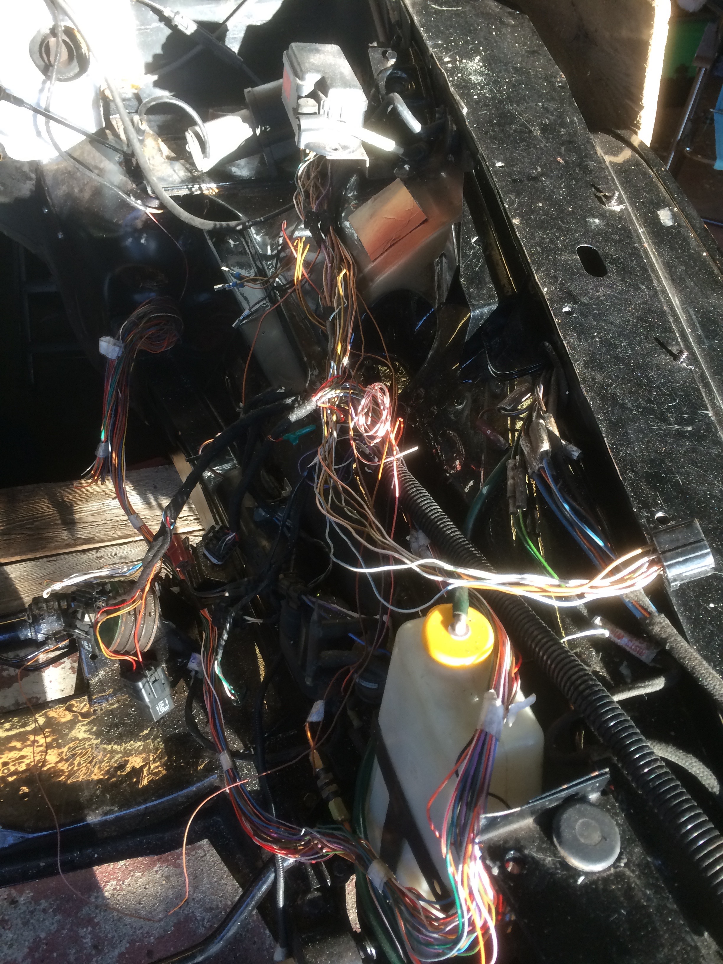
I had mucked up an earlier attempt at respraying the passenger side of the engine bay. Firstly I had covered part of the inner wing with tape around the VIN plate so that needed redoing and I also scratched the side during the fitting of some of the new items needed in the engine bay. You can see the initial repairs highlighted by the red primer and can also see the new wiring (temporarily laid out).
Side view temporary wiringTemporary Engine Bay Wiring
Rather than repair it and then damage it again as I carried on working on fitting the items and the new wiring needed in the engine bay. I also needed to cut a hole as that discussed in the cutting a hole in the bulkhead post.
Respray Preparation
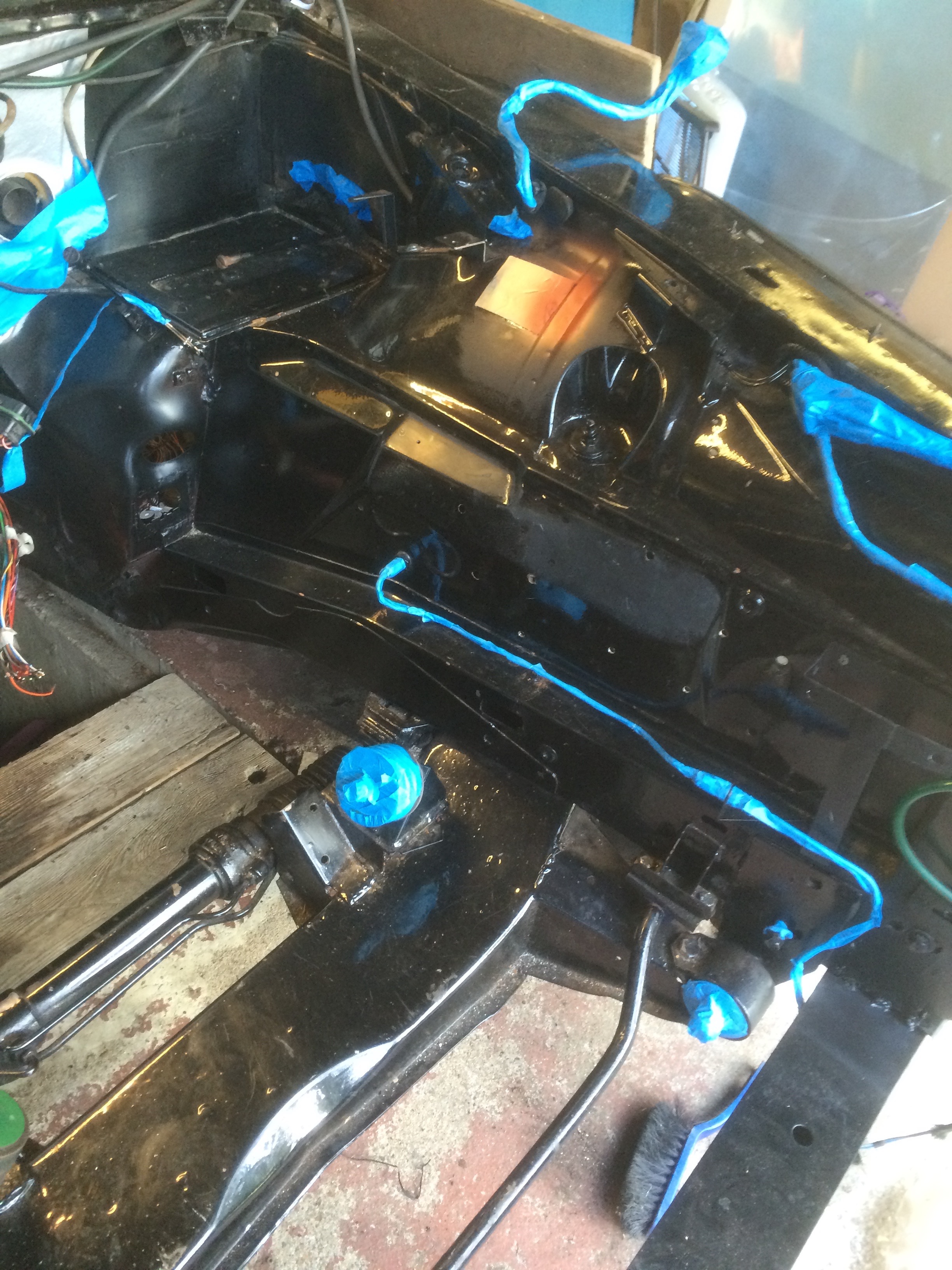
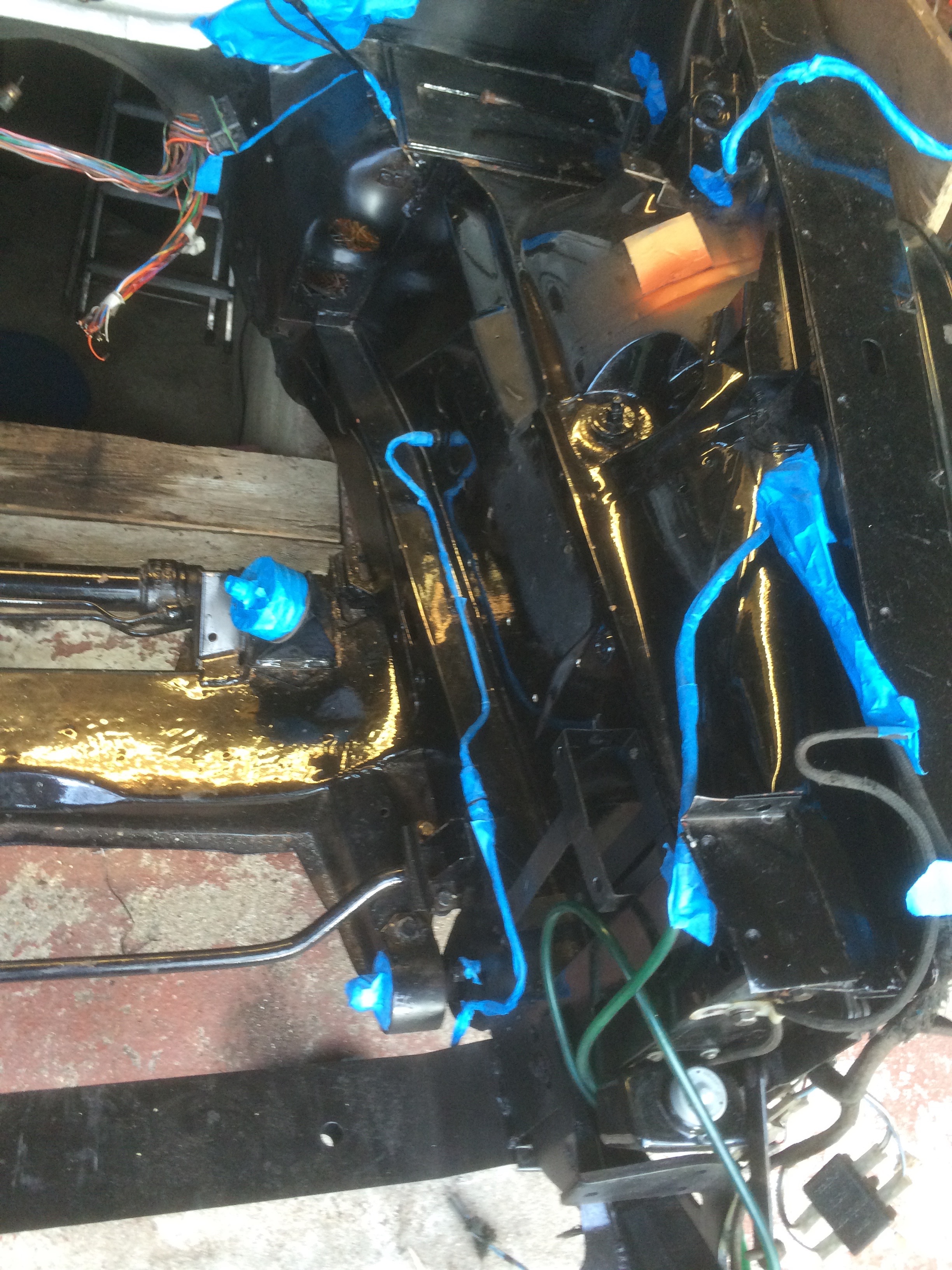
The first step was to remove the new wiring, the fuse box and the newly added modules to allow for the respray. The blue tape masks off the various parts I did not want to remove.
Taped up, prepped for sprayingFront view, prepped for spraying
Well I tried to respray it and obviously had some setting wrong because no matter how delicate and fast I was, I still ended up with a significant amount of paint runs. I guess I am a better storage technology guy than a paint sprayer 🙂
I have left it for now. I will carefully wet sand out the paint runs and see what it looks like in a week or so. stopped there as I decided to write this and then look to see if I can find some of the items I need to purchase.
Here is my current list of items to locate and buy next.
Reconditioning kit for the steering rack plus the bellows
Front shocks
Front suspensions ball joints
Alternative fuel pump as the ones in the twin tacks will not provide enough pressure on their own
need some more thought regarding the fuel system such as can I use the XJR tank or do I use a surge tank as suggested by Larry Louton on the Jaguar forums page
The rubber pipe that connects to the battery tray and the air inlet by the windscreen (BD4654) because mine is split
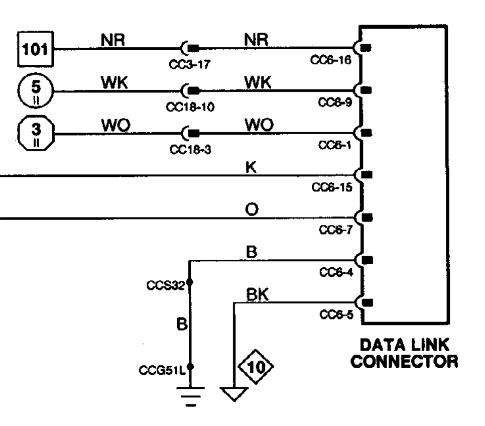
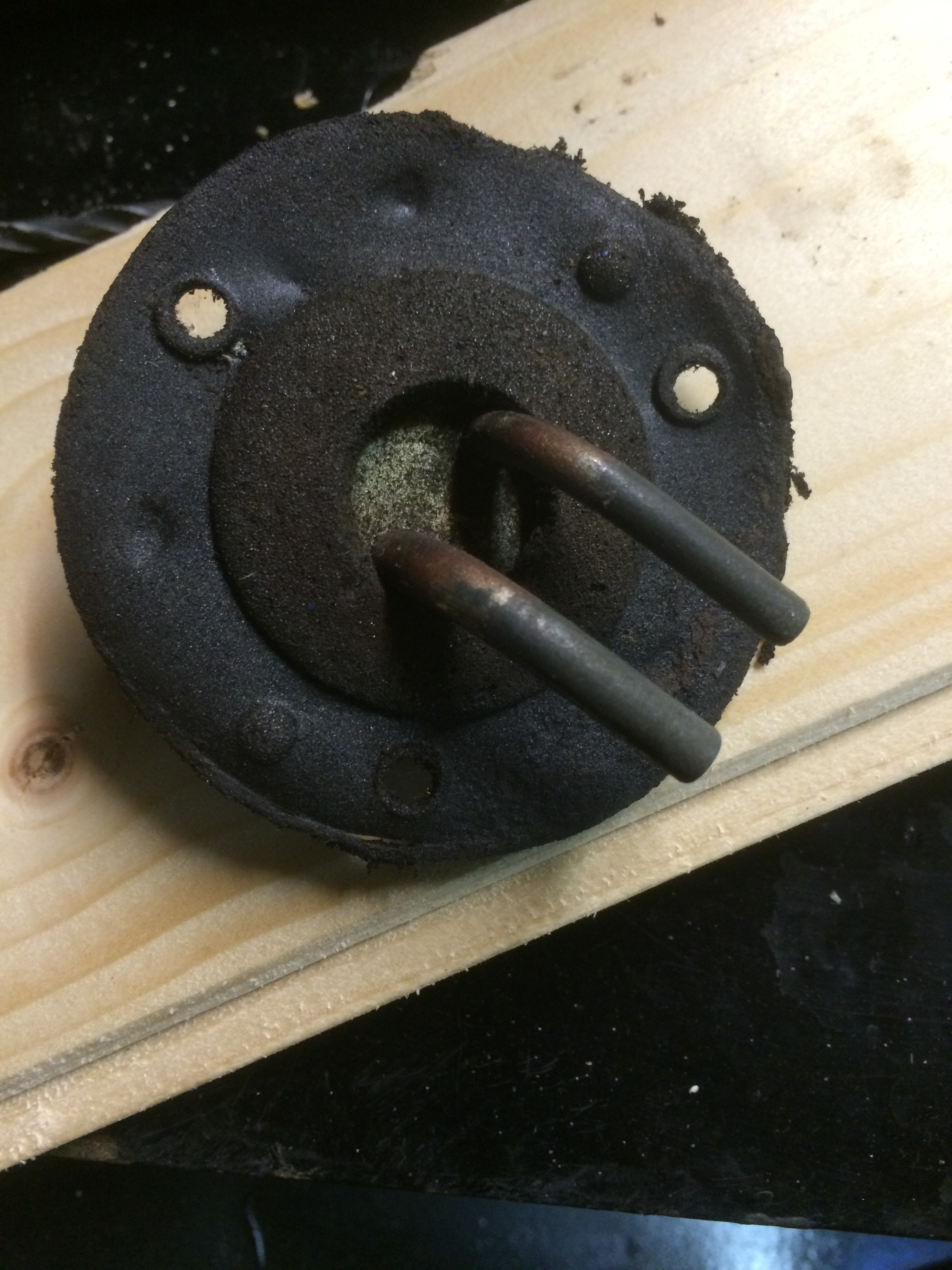
I spent some time in the garage over the weekend. Most of it was spent inspecting the Brake Master cylinder for the car. I had a pair of these for the XJ6. One I rebuilt, maybe 15 years ago and put in a drawer and the rusty looking one that was the original still in the car. The rebuilt one looked OK externally but had the wrong rubber fittings on the top where the reservoir should sit. It had the two identical rubber fittings that I believe go to the later versions of the car. These had a separate reservoir attached to the bulkhead via two pipes. My car has the reservoir fitted directly on top of the master cylinder. I had problems getting the pins out that hold the reservoir onto the master cylinder. I ended up cutting and eventually drilling out one of the pins. I then started to disassemble the cylinders themselves. The original master cylinder was very rusty and took a little persuasion to disassemble. Having removed the first of the two plungers, a quick look inside at the cylinder wall proved that it was beyond repair. I think you can see the rust damaged cylinder walls in the photos.
Original Master CylinderThis was the spare, no good either!
I then started on the one that had new rubbers fitted years ago to see if that was in a usable state. Unfortunately not! It looks like a new master cylinder is needed. They are no longer available from Jaguar Heritage. A quick look through the suppliers I often use reveals that there are superseded items available. Not a cheap item but better safe than sorry!
ODBII Socket
As I could do no more to the braking system, I spent a while reviewing some of the wiring and finally decided where I would place the ODBII connector. It is going to go inside the drawer in the central arm rest, between the driver and passenger seats. Not too difficult to wire up, deciding on where to put it took longer than wiring it 🙂 I was initially looking at somewhere under the dash but the centre console seems a better place. I will no doubt require access to it quite frequently, at least in the initial stages of installing and getting the engine running. I still need to check for clearance under the drawer as there are a couple of large pipes feeding the heating/AC flow to the rear of the car. I have left a fair amount of slack in the wiring to allow a lot of positioning options just in case.
There are just a few connection needed.
OBDII Socket wiring
Brown/Red – Box 101 is a fused but constant +12v supply
White/Pink – Circle 5 is a switched +12v when key is in position 2 which is normal running position
White/Orange – Hexagonal 3 is a switched ground signal also when the key is in position 2
Pink and Orange are CAN bus serial data lines
Black is chassis and Black/Pink is logic ground.
I had previously wired/reserved the constant +12v, and the switched +12v using the fuse box I installed into the passenger foot well by the door hinges. I had also implemented a relay to provide the switched ground connection elsewhere so I just tapped a wire off of that feed. The rest were either available to tap into around the J-Gate assembly or running across the area to get to the Instrument PCB. The Instrument PCB is going to be installed vertically on the drivers side of the centre console.
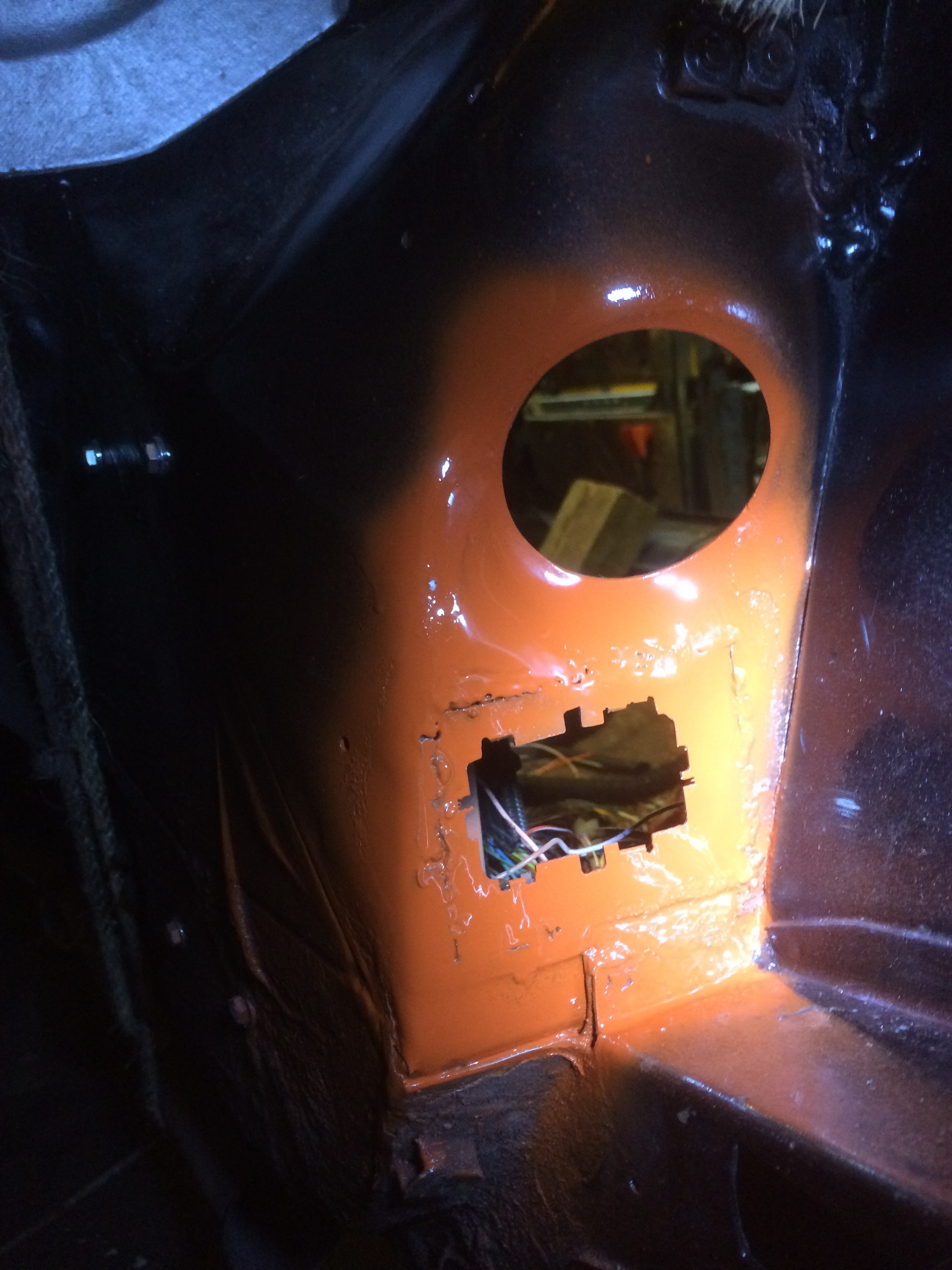
To get the ECU loom from the engine bay into the passenger foot well I needed to make the LHD steering column hole larger. This hole is used to feed the engine vacuum to the AC unit to drive the various flaps and valves.
Vacuum pipe panelStrengthening ring (after cut out)
There is a thick strengthening ring surrounding the standard hole so I decided to cut around that meaning the hole would be around 60mm in diameter. The plugs on the loom would not fit through the standard hole as they are quite bulky.
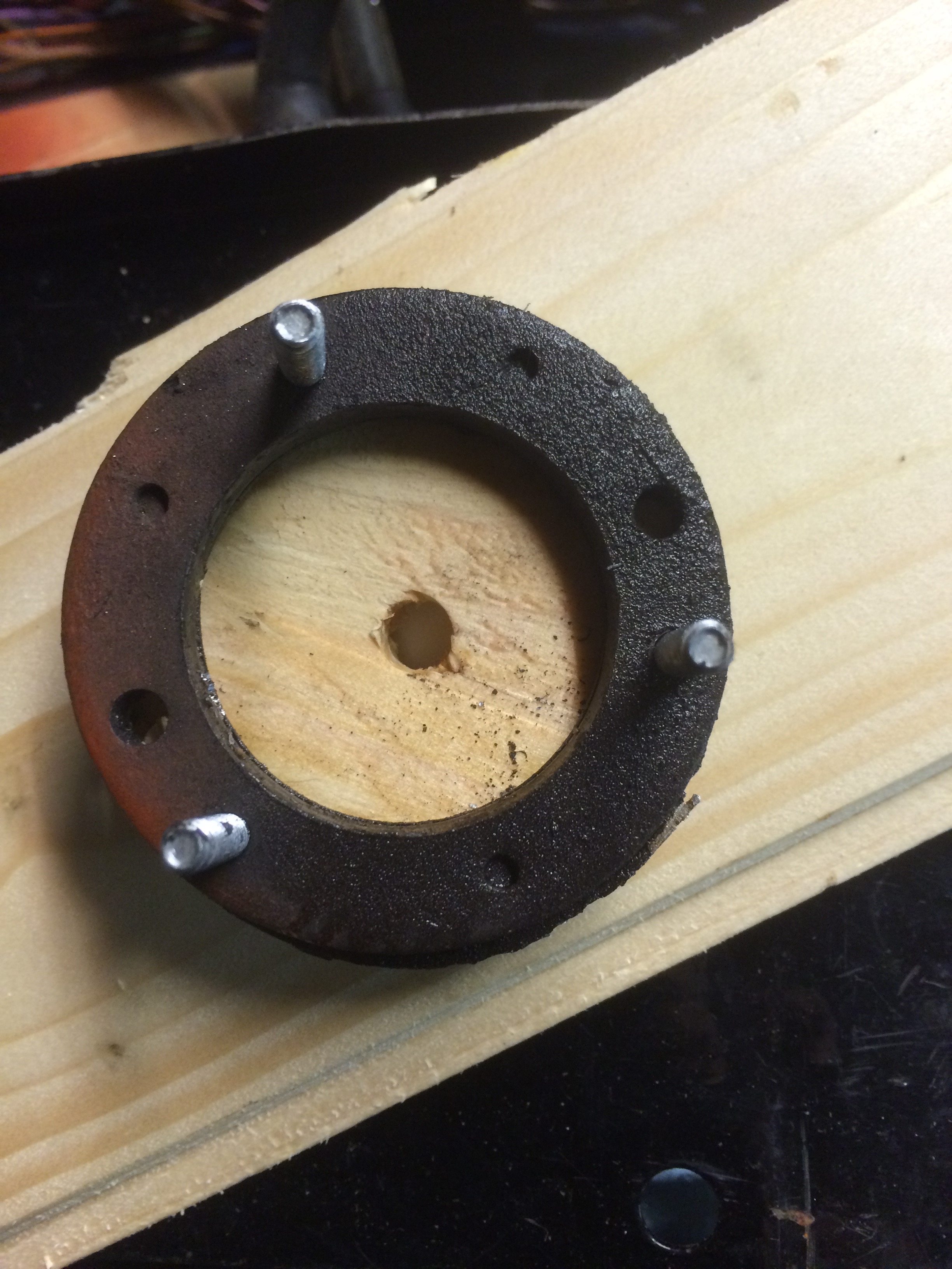
ECU PlugsWooden template notice the bulkhead cutout below it for the other required connections
I had to make up a simple wooden template to enable me to centre a holesaw in the right place. The holesaw, along with some cutting fluid made short work of the sheet metal and I was left with a nice clean cutout. Picture taken after a quick clean up and a bit of paint for protection.
Hole cut out
I will be using the rubber gaiter/plug to seal up the hole as used on the original XJR.
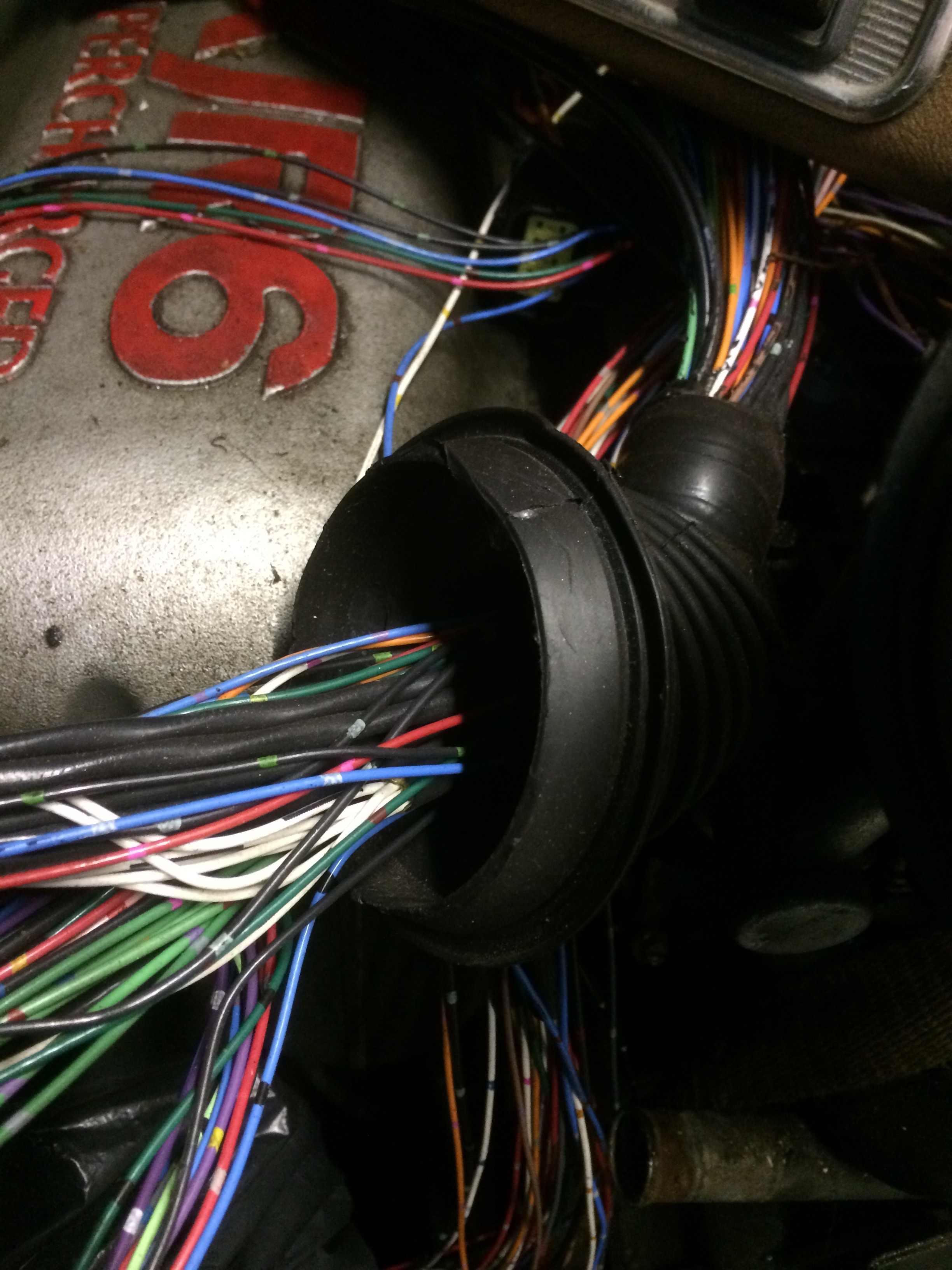
As its minus 3 degrees outside I decided not to go work in the garage so I’m writing up some of the work I did last year. As I already discussed hereI am attempting to use the minimum of the electronics from the original XJR without having to install all of the wiring as it was a lot, as you can see to the right! The main controllers I need are the following:
Engine Control unit (ECU)
Transmission Control unit (TCU)
Body Control unit (BCU)
Security and Control unit (SCU)
Instrument Display unit
Now I obviously have these from the XJR along with all the wiring however however I am not going to use all of the rest of the systems. That will of course cause some errors but I am hoping that I can resolve enough of them to allow the engine to run without going into limp home mode. The basic goal is to make the electronics think that it is still in the original XJR with some issues but not enough to shut the engine down.
For example, I need the SCU plus the module that senses that the key is in the lock to unlock the engine immobiliser system. Well I don’t need the actual lock from the XJR. In fact, all I need is to place the key (or just the RFID chip in the key) inside the coil that was around the key lock for that to signal the system that the key is there and to unlock the engine inhibitor.
Another example is the central locking and the door lock sensor system. I am hoping that I can just tie all the signals to either high or low and trick the system into think all is well.
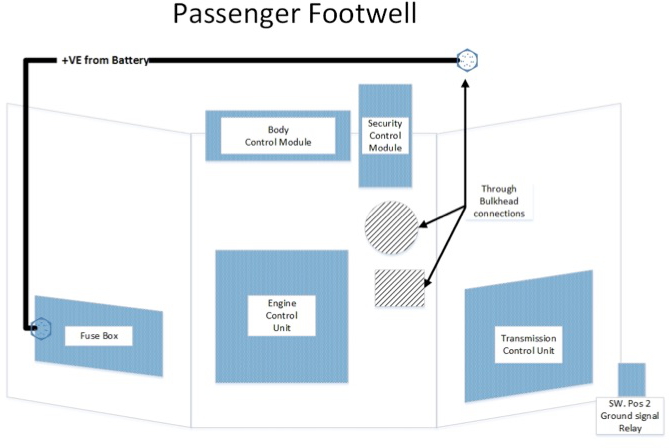
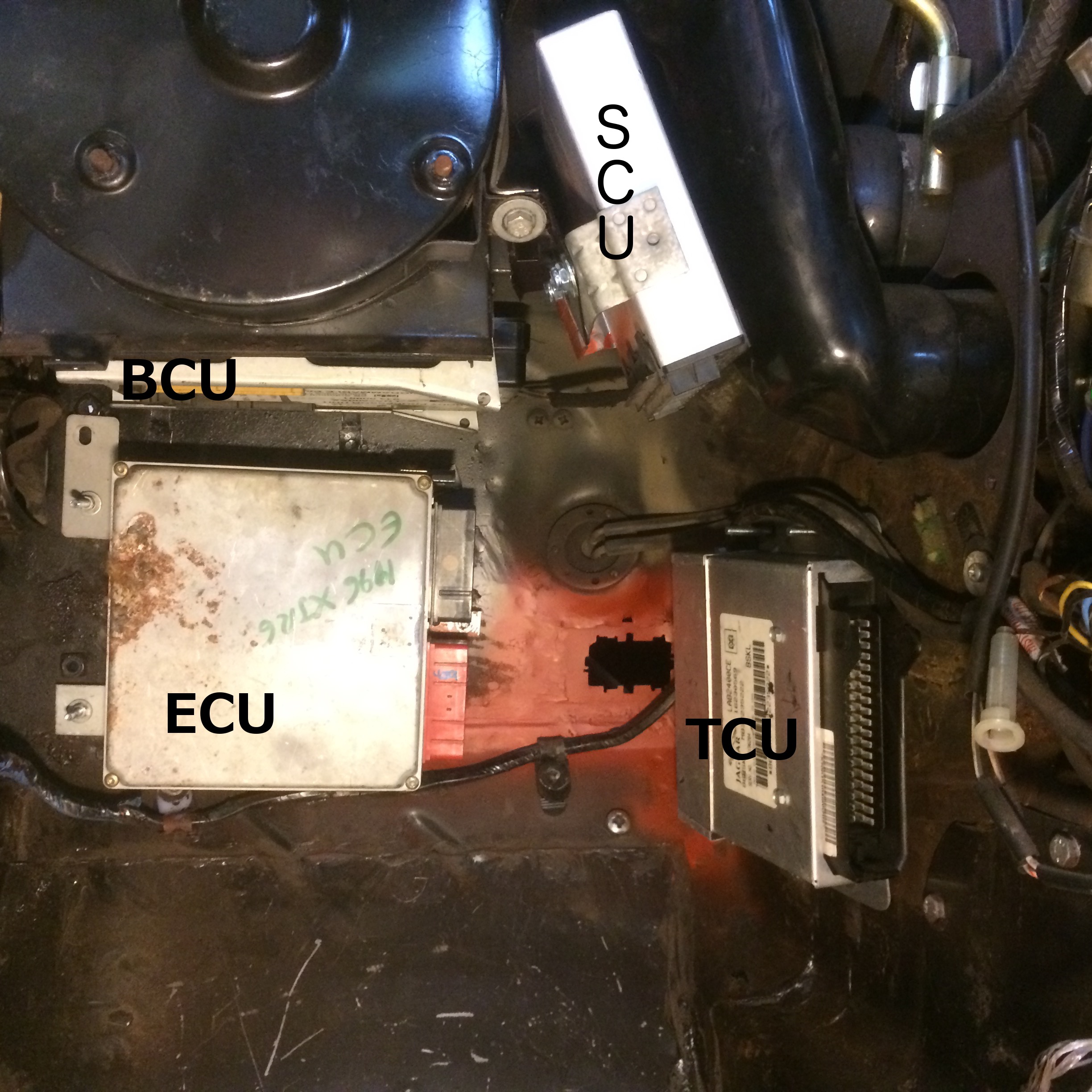
There are a fair few modules that I need to mount somewhere and a lot of wiring that I need to do. I am putting the modules in the passenger foot well. After a lot of thought and trial fitting I have installed the control units as follows.
ECU vertically where a passengers soles would go. I plan to put a false panel across this area covering/protecting the modules.
TCU Vertically, to the Right hand side of the foot well
BCU Horizontally, directly under the battery tray between the bulkhead and the round Fan assembly
SCU vertically and at an angle between the round Fan assembly and one of the output pipes.
I also installed one of the XJR Fuse boxes into the left hand side of the foot well behind the door hinges and powered from the through bulkhead bolts used to distribute DC positive power into the interior.
The layout can be seen in the images below:
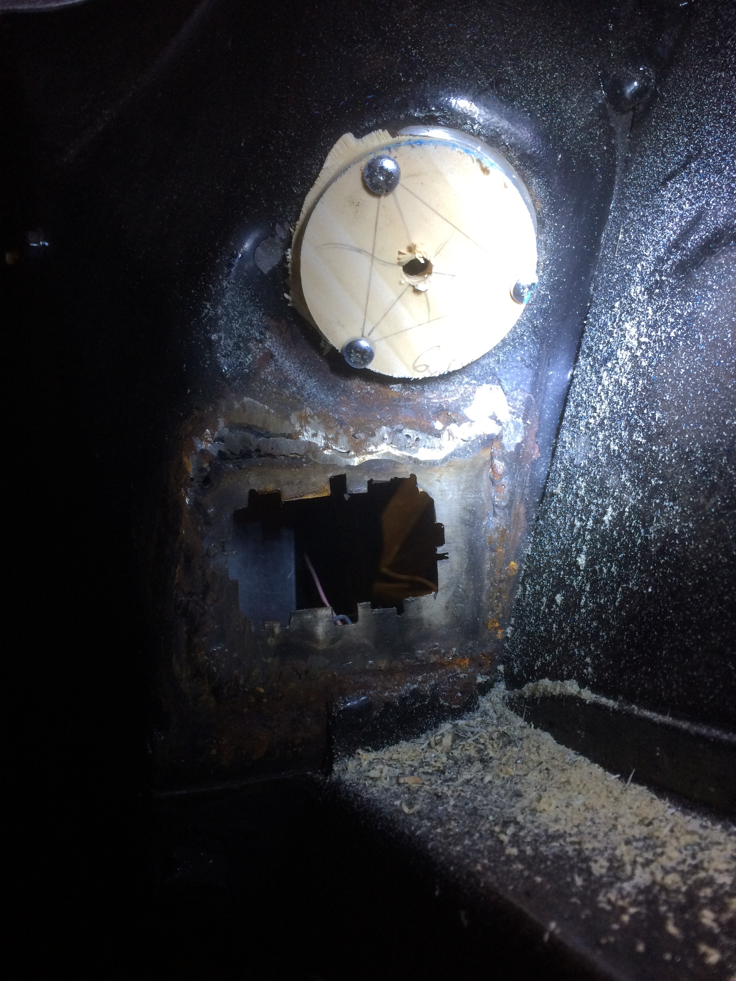
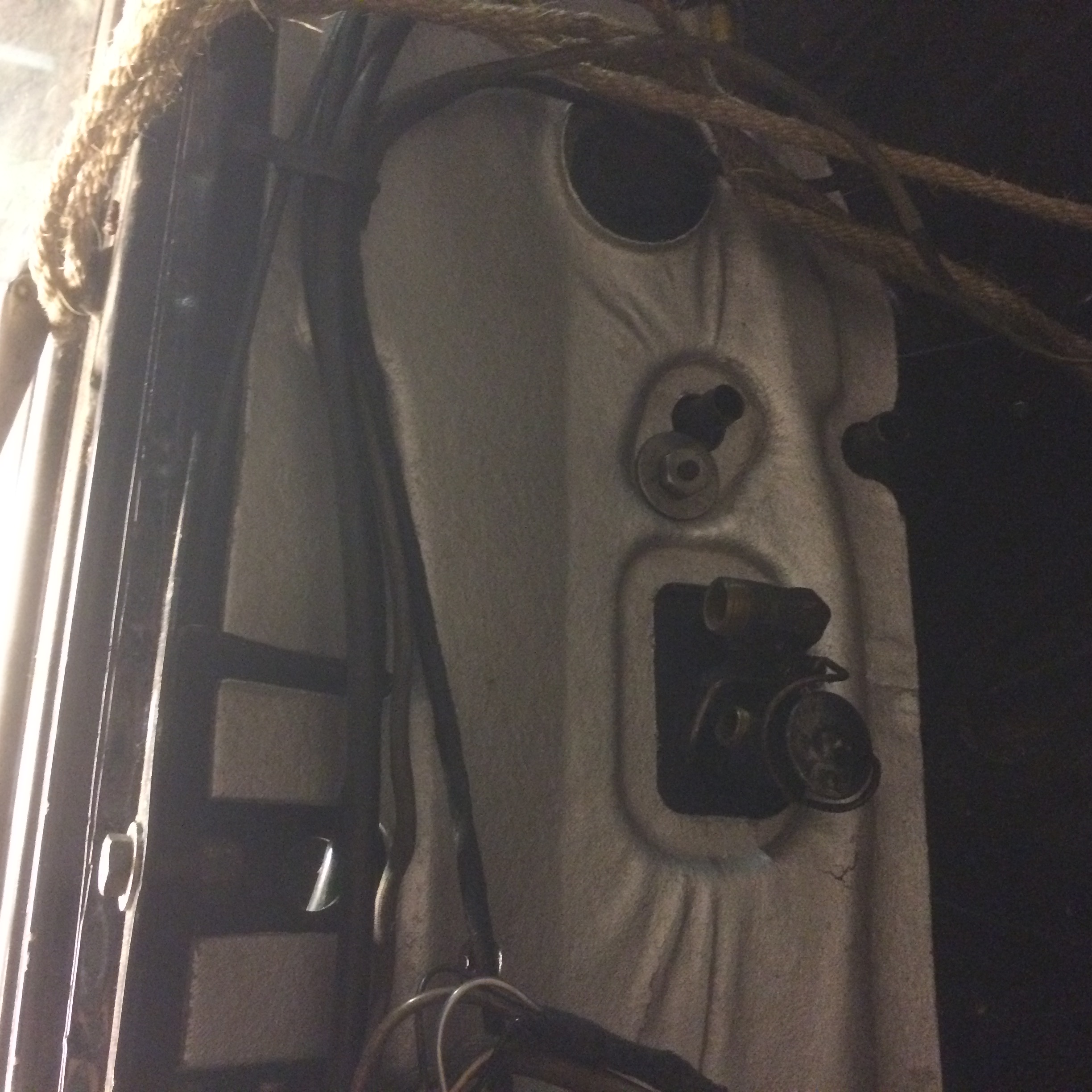
Control unit locationController Unit locations in footwell.
Above, you can see the inserted panel (red paint) with the rectangular hole for the through-bulkhead connector. I had to make quite a complex and accurate hole in the bulkhead to get a good fit for the bulkhead connector as used in the XJR. I should have cut it out of the XJR body but I scrapped the body without thinking about it. It was easier to make up a small panel on the bench with the required cut out and then weld the small square panel into the XJ6 than try to do it upside down in the foot well. The circular item above the red painted area with two pipes in it, is the access point for the Vacuum pipes from the AC unit. That is the hole used for the steering column on a LHD car. I will use it to get the ECU plugs and cables from the engine to the ECU. I will actually have to cut out the outer edge of this factory made hole as the plugs are quite big. There is a rubber gaiter on the XJR loom which should make a nice fit into this hole keeping the engine bay fumes out of the interior of the car. having to make these holes is a shame as I really don’t want to make too many changes to the body as part of this modification.
At least I stayed warm this evening. I hope the weather breaks soon as I have not really done anything to the XJ6 since New Years day. I did work on the XKR regarding the tweeting. I have however, earned some brownie points doing quite a few DIY jobs in the house.
There was a strange tweeting/squealing noise emanating from the engine bay on the XKR which started a few months ago. It stopped once the engine got warm. I did mention it at the last service and they changed the Supercharger belt. The nest full of hungry birds returned shortly after the service. I tried using a tube and an old funnel to isolate the noise which I deemed to be the water pump. There was some notoriety with early water pumps so I changed it before Christmas. The noise did stop for a couple of journeys however it returned again! Not needing to use the car for a little while, it sat while I decided what to do next. A friend of mine from the JEC (Thanks Neil), lent me an electronic listening device which has a long tube that you place onto the various parts you suspect are making the noises and listen via a pair of headphones. You could not hear the tweeting but a rumbling noise and some were worse than others. One of the tensioners was noisier than the rest so that was the initial target.
I did a little research and there is a replacement tensioner and idler wheel set for the princely sum of £200. The set also included the Supercharger belt which I had just changed so I did not want to go down that route. I then came across a post on a Jaguar forum.
The solution is to replace the bearings in the various wheels and idlers and the post included details suitable part numbers. I ordered four bearing for a total of just over £14 so a big saving. I changed one idler wheel bearing without removing the Fan assembly but you do have to remove it so you can get to the bolts holding some of the other idler wheels on. This is reasonably straight forward.
Ratchet Spanner from Aldi
Once you have struggled to get the two nuts off of the fan assembly, they are not tight or anything just there is no access to them. I used a small ratchet type ring spanner that also could be angled enough to get into the tight spot. (from a cheap set I brought myself last time I was in Aldi)
I removed the top plate holding the radiator in position and I found I needed to remove the top radiator hose and the air filter top to allow the Fan Assembly to be juggled out of the way. Once the Fans were out of the way you can undo the various wheels as needed.
I used a socket, a long threaded bolt & nut plus a large metal bar to pull out the bearings and tapped them back in using a suitably sized socket and hammer.
Made famous by Haynes, Reassembly is the reverse of removal, and once all back together, topped up the coolant that I lost disconnecting the pipe and went for a test drive. All seems well except for I started the engine with the plug into the air box unplugged so I have an engine MIL light illuminated. I’ll see if it goes off on its own after a few journeys otherwise I’ll plug in the ODB2 device I have and turn it off myself.
Back on the road and no tweeting …. for now anyway!
No good 🙁
A couple of days later, the noise was back see the video below:
Welcome to 2016, hope it treats you well and you keep healthy 🙂
I did spend a little time in the garage on New Years Day and did some work on the XJ6.
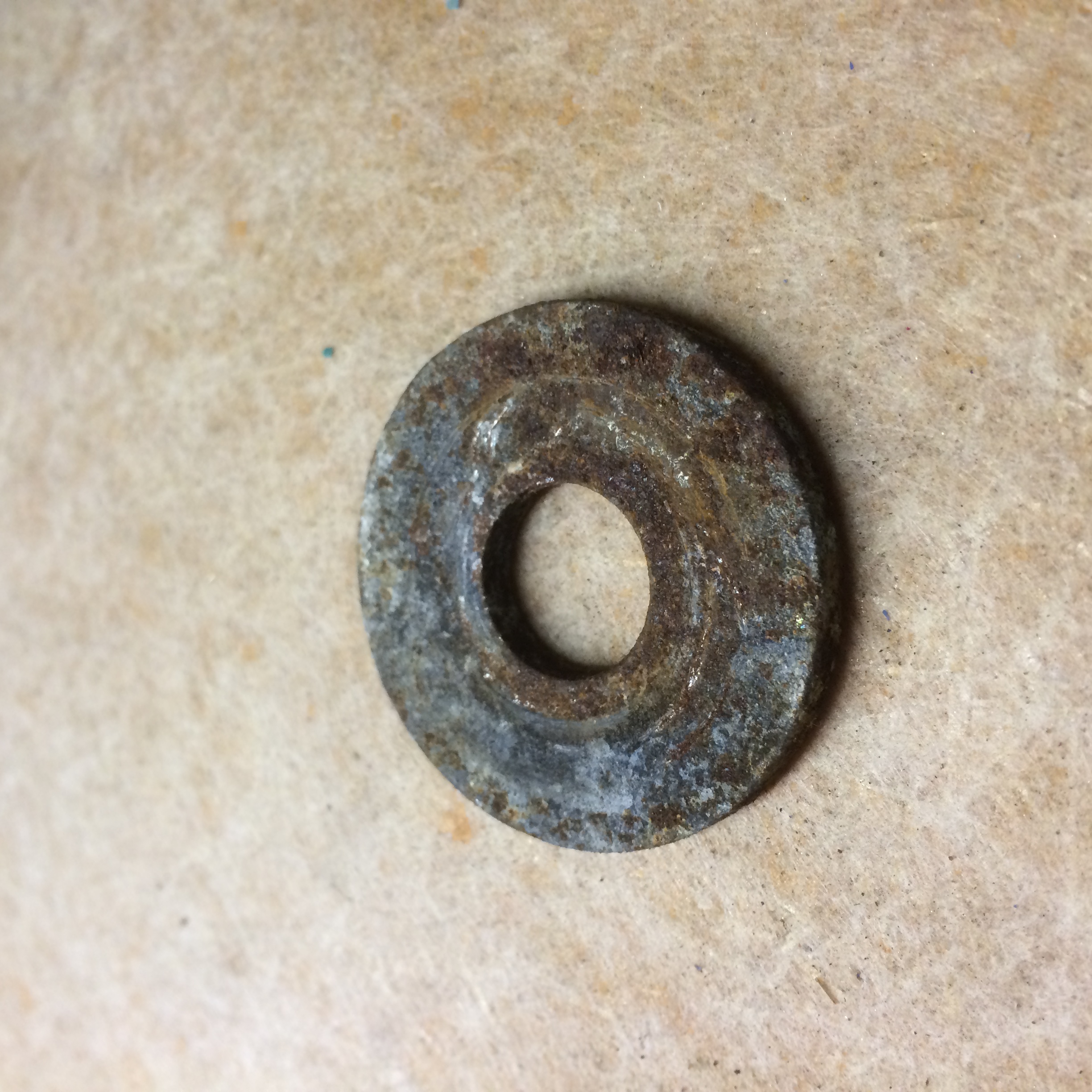
Cleaned up and sprayed a bit of clear lacquer onto the two washers and large nut heads that are used to hold on the bulkhead heat insulation panel. See the before and after pictures below
I also tidied up the wiring a little
Made up a gasket, found some suitable bolts and installed the brake pedal assembly and servo unit.
Washer “Before” imageRight hand “shiney” Nut & Washer